R1G133 Industrial Fan Laptop Cooler
Over the summer between Grade 12 and University- Summer 2026- I worked on a laptop cooler to achieve two goals: The first: to gain a better understanding of full-system design and completed engineering projects; and second: to test what my laptop was actually capable of if it didn’t have to worry about heat, which was something I had wanted to investigate for a while.
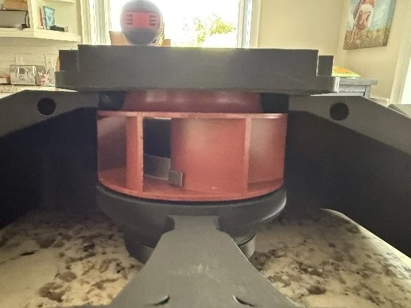
Starting this project meant fan selection, which had a few layers to it. I sliced the process into a few different sections to make this easier and to better meet the objectives of this project. First, I wanted to select a fan type- something like axial, centrifugal, or blower-style. What I chose was a centrifugal fan exhausting air radially, as this configuration provides a few benefits over the typical axial fans that you might see in a computer case or regular ventilation systems. The main reason that I decided upon a centrifugal fan is that they tend to move air much more efficiently in high-resistance environments compared to axial fans, and a laptop’s grilles and cooling fins are a high-resistance environment. Looking at centrifugal fans specifically, I had to decide which type of centrifugal fan to use- a forward-curved or backward-curved centrifugal fan- and I also had to determine whether I wanted to use AC or DC power. The first selection was easy- forward-curved fans excel in lower-pressure and lower-noise applications compared to backward-curved centrifugal fans, while backward-curved centrifugal fans dominate in high-resistance, high-airflow systems, where noise isn’t as much of a concern. For me, I wanted the best performance I could get out of a compact, relatively expensive fan, so I chose a backward-curved centrifugal fan type. I also chose DC for my fan because it would be a bit safer than AC power, and I was able to source an inexpensive AC-to-DC wall adapter off of Amazon. From there, I only had to select the size and footprint of the fan. For convenience, I wanted to select a smaller-diameter centrifugal fan, as it both decreased cost and kept the full cooling unit in a somewhat smaller package, although it did still keep the cooler impractical for daily use.
With everything I had selected in mind, I had enough information to look for a fan. My only constraint was that it had to have enough documentation that it would be relatively easy to set up and use. For about a week, I was searching around AliExpress and looking up different fan models, but every good fan I found either was too expensive upfront, had a very long lead time, or had incredibly high shipping costs. After enough time searching, though, I found an EBM-Papst used fan from the US for cheap, with cheap shipping costs too, from a used electrical parts shop. This particular fan was the R1G133-AA17-08, and it was the one I ended up choosing. EBM-Papst is a reputable fan company that manufactures high-quality fans of a few different types in Germany, and if I were to get this fan new, it would have cost me $300. Because I got it refurbished, though, it was only $30, including shipping, while retaining 90% of the performance and functionality of a brand-new fan.
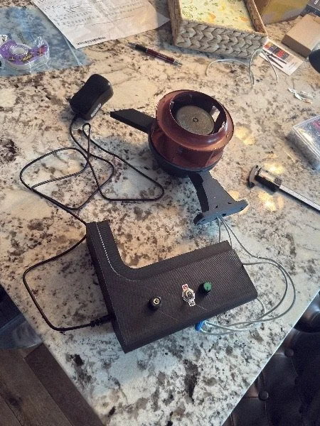
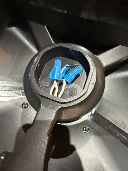
Immediately after I selected the fan I was going to use, I began work on the project. Before I started developing the main 3D model for it, I needed to figure out which exact electrical components I would need to get this project to work, and I also had to find a model which accurately portrayed the dimensions of the fan I chose. The first part was easy, as the datasheet for the fan showed various electrical circuits for controlling the fan, and I ended up using a control voltage option, where I left the tachometer wire on the fan unused and controlled the fan without any output. This was a fine setup, especially for testing and as a non-commercial product, as I would be using the fan at max speed for benchmarks and not much else. For this setup, I only needed a potentiometer, switch, and a dedicated 24V to 0-10V adjustable output module, which I was surprisingly able to find easily on Amazon for cheap and in a small footprint. Unfortunately, nothing I chose had a readily available CAD model, and one of the electrical components was lacking an accurate physical datasheet. To combat this, I measured that component- the adjustable voltage module- when I got it, using callipers, and recreated the main design and connection points as a separate part in CAD. Alongside that, I was able to recreate the potentiometer and switch, which I later learned used standardized mounting processes for those components. The fan was the most difficult to recreate, however, as I was only able to find the physical dimension datasheet for the AA17-02 model, not the -08 model that I had; these two had slightly different dimensions, which I had to check individually for my CAD recreation of the fan. Eventually, though, I completed each required model I needed to begin development on the main cooling stand, and I started the design in Fusion360.
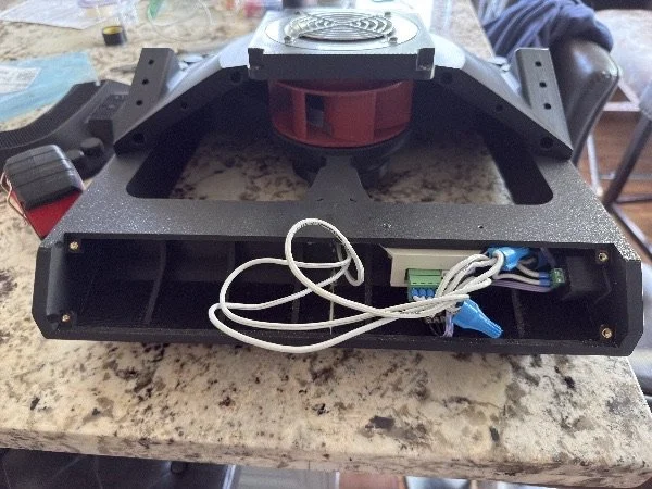
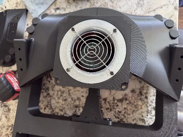
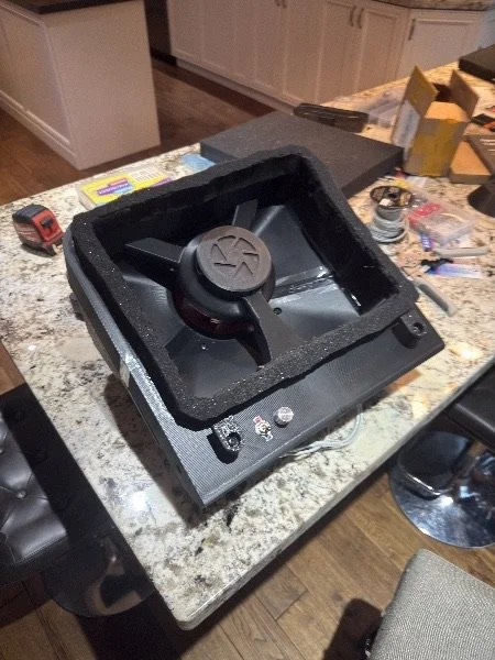
Once I began work on the model, I quickly recognized three main sections I would need to focus on independently: The structure of the cooler, ensuring it could hold each component and the weight of the laptop sitting on top of it; the plenum that would transition the fan’s tight radial exhaust into a wide linear airflow against the bottom surface of the laptop; and the foam gasket that would seal the laptop against the laptop cooler, ensuring the airflow goes primarily through the laptop, and not around it like a non-pressure laptop cooler.
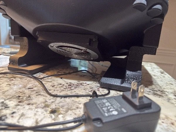
To begin with, I knew I had Elegoo PLA+ filament that would be making up the bulk of the laptop cooler. Furthermore, the laptop cooler had a large plenum and a lot of space to add legs and support for everything, so FEA was not required, and I simply took a sensible approach to designing the frame of the laptop cooler, with the foreknowledge that I would be using 15-25% gyroid infill during printing, rather than a solid mass. The main issues with the structural design of the cooler were due to the fact that I would be unable to print most sections in one seamless piece and would instead need to connect them together with some medium to ensure they were accurately oriented and would not shift while being bonded. I had the idea of using printed dovetail joints, but figured it wouldn’t be the best method due to the number of parts that would need to be connected, and the fact that multiple parts would need to be connected in different orientations to a single part, so dovetails could not be oriented favourably for all parts during printing. The next idea I had was to use 3D-printed dowels, but I realized they would be worse than wood dowels because they would only fit the parts together and wouldn’t provide an extra hold like wooden dowels hammered in would, with a slightly tighter tolerance. Because of this consideration, I did decide on wooden dowels and glue for the joining method, clamping the parts together while the glue dried. During the slicing process, preparing for printing with all the dowel holes for components, I realized that the dowels would provide another benefit- they would have fibres running in the opposite direction from the 3D print lines on some connections, which would provide extra structural reinforcement. During the design process of the stand before slicing, I also had to take into consideration other aspects as well: serviceable parts, wire guides, component mounting, and the joining of non-glued and dowelled connections. Each of which was a different challenge to tackle, and each was done with an iterative process- finishing multiple, then going back and reviewing my designs. For the joining of non-monolithic parts, it was primarily done with M5 brass heat-set inserts, which allowed parts to be screwed together at multiple contact points.
The plenum was a separate beast to tackle and was done in a relatively early stage of the structural design process. I set up the exhaust edge of the fan as well as the top rim of where the laptop stand would connect to the laptop (roughly, just where the foam seal would start). I first experimented with a G2 loft between the components, modifying the tangency weight but never able to find a balanced curve which I liked. Instead, what I ended up doing was first making a simple box formed from the connections, doing a simple large chamfer, and then adding two medium-sized G2 fillets on each edge of the chamfer, providing a more gradual and realistic expansion for the airflow. This was not strictly necessary, as the fan would be overkill even with a badly designed plenum, but making sure to develop a sensible plenum design ensured the airflow was much smoother and would make the cooler a bit more effective overall, so it was worth the extra design time.
Finally, the easiest integral component to design was the foam seal between the laptop and laptop cooler. All I had to do for this was design a lip for the foam to be cut down to fit into, eventually being glued down. For this part, though, the most difficult choice was the type of foam. Open-cell foams would be much lighter and cheaper, but closed-cell would allow for a tighter seal and much less air leakage compared to an open-cell foam seal. After researching, though, I realized a closed-cell foam wouldn’t be able to form a good seal with only the weight of the laptop, as they typically take much more compression force, and the foam could potentially just act like a solid block- giving more air leakage compared to open-cell foam, not less. Because of this, I shifted my research to an open-cell foam design and ended up getting typical black open-cell polyurethane foam, as it was the cheapest and would provide a good seal against the laptop, with little air leakage attributed simply to its open-cell nature.
Printing took a while, but was relatively seamless for most parts, only failing due to a few issues with printer calibration, not with part design. Everything fit together well the first try, and I was surprised at how quickly I was able to get the unit ready to test. Before I give the before-and-after results, it’s good to know my laptop’s operating point. It has a 250W TDP, giving up to 175W for the GPU and 160W for the CPU (albeit not at the same time). For the thermal benchmarks, I ran Cinebench GPU and CPU multicore simultaneously and recorded temperatures and usage with HiWiNFO64. Running these benchmarks before capped the TDP at 200W due to thermal throttling from both the GPU and CPU, even with the internal laptop fans running at max speed. The temperature of the GPU hit 85 degrees celcius, and the temperature of the CPU hit 99 degrees celcius. After mounting the laptop on the cooler and running both the internal laptop fans at full speed as well as the cooler fan at full speed, I ran the same benchmarks. This time, I was able to draw the full 250W from the laptop’s power system and had the GPU running at 150W at just 50 degrees Celsius, and the CPU running at 100W at 60 degrees Celsius, meaning the cooling system gave the laptop a big improvement over its typical thermals. The laptop also performed about 10-15% higher than the runs without the cooling system attached, which was nice to see as well.
Overall, I would mark this project a huge success- it was able to cool my laptop effectively at its max power distribution, and I was able to learn a lot about full-system engineering by completing a full project like this. While it was satisfying to see everything come together, the cooler runs at an unbearable noise level, which is audible in the video above, and I have a few takeaways from this project if I were to ever do it again. If I had the chance to revisit the project, I would definitely select a forward-curved centrifugal fan, due to its lower noise while still performing incredibly well compared to a typical axial fan of the same diameter. Additionally, I would probably try to reduce the structural support on the cooler a lot, as while it was nice not to have to worry about the structural support during the design phase, I did waste a lot of unnecessary filament due to it, and the final product ended up being very blocky. If I were to redesign it from scratch, I would also have picked a new fan instead of a used but higher-quality one. This is simply due to the unit degradation of a used fan, which increased the noise considerably beyond what the datasheet specified for a new fan unit.