Electronic Flying Wing UAV Project Part 1
After completing High School and getting school licenses for Autodesk Projects with my McMaster Email, I wanted to start work on a major project for my portfolio before school started. My intent was for this project to be finished quickly, but also to be a culmination that would showcase all of my multidisciplinary skills and CAD expertise. My portfolio until now had been filled with my high school tech design projects and other focused projects I did on the side, and I had never done a long, full-stack design and research project. As I want to go into aerospace engineering eventually, an aerospace-oriented project interested me the most, although I was unsure what I should do. I had a few project ideas to begin with, but needed to narrow my selection to a single project which I believed would show technical depth, would be interesting to work on, and would be relatively quick. That last assumption for this chosen project was so incredibly wrong, but I still believe I have gained enough experience with part one of this project, completed between the end of my Grade 12 year and the beginning of university. The projects I was choosing between were mostly drone and rocketry-oriented. A friend from high school had talked a bit about making a rocket during the summer, but the idea fizzled out once summer actually started, although I did seriously consider this as an option. Unfortunately, compared to the other projects I could do, a rocket simply didn’t interest me much, and I did not know the laws surrounding hobby rockets in Canada. Another option I had was to complete my J52 jet engine first-stage design from high school, but I ended up deciding that doing that wouldn’t provide as much benefit as a completely new project, focused around something I might actually encounter to design in the next few years. From there, two main projects interested me- both drones: an FPV drone and an electronic fixed-wing UAV of some kind. I chose the fixed-wing UAV because I am much more interested in eventually going into aircraft design, and not so much FPV drones. I also might have been tempted to create the FPV drone in real life, which would definitely take extra time while restricting the scope of the project, and making a large electric UAV would keep the design purely in CAD and on paper. This seems like a strange constraint to have, but creating this project- one I wanted to have great technical depth- would be counterintuitive to my goal, as manufacturing would take much longer than I had, and- as I said with the FPV drone- would likely constrain the scope of the project, restraining my full demonstrable technical ability.
After selecting the electronic fixed-wing UAV, I had to decide specifically what I wanted to do for the project. In the end, I did decide upon a complex configuration, which wasn’t ideal for a first fixed-wing design, but challenged me in an interesting way: a flying wing. Alongside the flying wing objective, I had to decide the other main objectives and features, each of which had its own selection process. The first of these to tackle was propulsion, and at first I had a few different ideas, including a central propeller, two propellers on wing nacelles, an external EDF, and finally an internal buried EDF. The reason I decided upon an EDF over any propeller was that I knew propellers created wash over the surface of a wing body, and that it energized the boundary layer, which could be great for a flying wing, but I also knew that counteracting this and simulating it would likely be beyond my technical capabilities at the start of the project. Beyond this, I wasn’t confident that I would be able to learn how to simulate this within two months, and it would end up complicating the external aerodynamic design. I also chose EDFs due to their packaging design similarity to jet engines, compared to typical props. From here, I knew I wanted to use EDFs of some sort, but didn’t know whether I wanted to use buried EDFs or externally mounted ones on nacelle pods of some sort. I decided upon buried EDFs because I wanted to showcase my experience with smooth ducting transitions, and believed that external EDFs would add a lot of weight and result in an unappealing design (Although bad design was the weakest counterargument and the one that had the least sway on my selection). So, I tentatively selected the EDF, but kept an asterisk on my selection document to revisit this option later, after the aerodynamic shell of the flying wing had been created. I still have the intent to complete this post-shell propulsion selection while designing the shell mainly for buried EDFs, and the reason I haven’t done that yet will be clear later on in this page.
So, with the aircraft’s shape selected and the propulsion temporarily chosen, it was now time to find an operating point and the operating condition of the aircraft. Despite the fact that I don’t have the intent to fabricate this aircraft, I still wanted to design it as accurately as possible, and a massive part of that means finding an operating envelope. To do this, I selected a speed I believe the aircraft should maintain at cruise- 35m/s, or just about 125 km/h. This seems extremely fast, but for efficient UAVs, speed is typically a big factor, as lift tends to climb with speed- or, more specifically, with the Reynolds number, with other variables controlled. Alongside this, I also had to set an endurance goal, which I decided upon 20 minutes for, although I would have to review that later with battery selection alongside the propulsion, as those were the two primary variables controlling the drone’s endurance.
Finally, after doing everything above- everything I thought I needed for the aircraft’s criteria-selection phase- I began work on the pre-design phase, keeping in mind the constraints and design options. have chosen. After doing a bit of research on flying wings, I found that a near-zero pitching moment with a negative slope would be best, so the airfoil selection would have to keep that in mind. Furthermore, as the aircraft reaches its stall envelope, I learned that it is crucial for the wing root to stall first, with the stall slowly moving to the wingtip so that the aircraft doesn’t lose roll control and the operator can correct the stall. Going into the first design phase, I didn’t do nearly enough research, but this was also the quickest design phase, and I was able to easily recover and move on after scrapping this first design.
A bit about the first design, however: I used 4 different airfoils along the length of the wing, from the central fuselage to the wing root, then the midwing, and the wingtip. I lofted between them cleanly, with a typical Fusion360 surface loft, and capped the wingtip off with a smooth surface patch shooting off the wings, with both G2 and surface continuity. When mirroring this wing part, it created a central seam, which I fixed with a small central G2 fillet, and, in the end, the aircraft looked a lot like a Ho229 from above. I had a methodology for selecting each of the wing cross-sectional airfoils, but at the time it wasn’t very sophisticated and relied mostly on finding those favourable Cm curves- weighing that much more than I should have- and looking for high peak Cl/Cd. These approaches have definite errors and weren’t great for selecting coherent airfoils, as the peak Cl/Cd didn’t mean each airfoil had its peak at the same alpha, and the high stress on the pitching moment made me miss out on a bunch of great airfoil options. My selected airfoils were: Liebeck LA5055 for the fuselage centre; US1000ROOT for the ‘wing root’ area of the wings; EPPLER 328 for the midwings; and RONCZ 1082 for the wingtips.
The LA5055 is part of a small airfoil family, and it is an interesting experimental airfoil. I planned to use its high frontal thickness to help to embed the EDFs, but I was missing one crucial detail about this airfoil- it was designed for very specific conditions. It struggles in flow where air is anything less than perfect across the airfoil’s surface, and in real aircraft and flight conditions, it wouldn’t be able to work consistently near its graphed characteristics. Additionally, the airfoil was heavily optimized and, because of that, requires near-perfect surface conditions. Beyond what the airfoil itself produces, it incites a lot of drag that airfoil analysis simulations don’t necessarily account for, and furthermore is optimized for a single narrow peak Cl/Cd. After this airfoil, the US1000ROOT isn’t a particularly bad airfoil if used correctly, but it was a bad choice for this aircraft. The important thing to note for it is that it is a symmetric airfoil and doesn’t produce much peak lift, while producing a lot of drag. Furthermore, it doesn't produce any lift near 0 degrees alpha, and the graph is symmetric around the origin, the intersection of 0 degrees alpha and 0 Cl, meaning that even shallowly negative alphas, the airfoil would produce negative lift. After that, the EPPLER 328 was used for the midwing airfoil. This airfoil’s characteristics were alright, with a gentle Cl/Cd graph, good near-zero Cm characteristics, and high peak Cl; although the shape of the airfoil is interesting, it would have been difficult ot manufacture, and was much too thick a selection for the midwing airfoil. The final selected airfoil was the RONCZ 1082 tip airfoil, which is another airfoil with good Cm characteristics but a sharp Cl/Cd curve, as well as a relatively early stall, which isn’t desired for a wingtip airfoil on a flying wing. While each of these airfoil choices alone has been questionable, the biggest issue stems from using them together. As I stated earlier, every airfoil is lofted together as smoothly as possible- in this case, each lofted section creates such an extreme shift that the performance of the cross-sections between main airfoils is likely abysmal, especially due to the large shape changes between every airfoil section in this wing. Although the loft may be continuous and smooth, the behaviour of the airfoils and wing doesn’t follow that same trend.
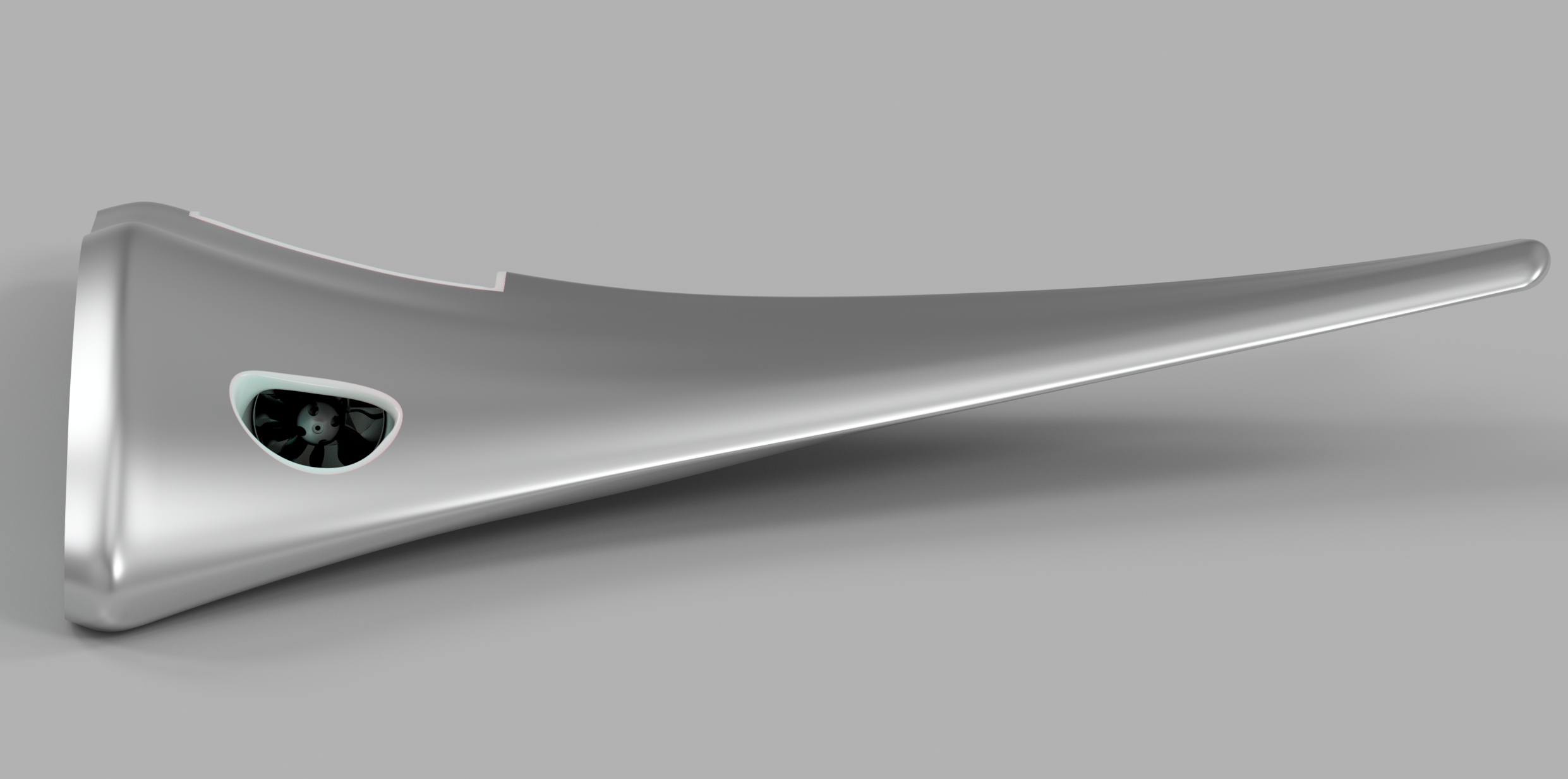
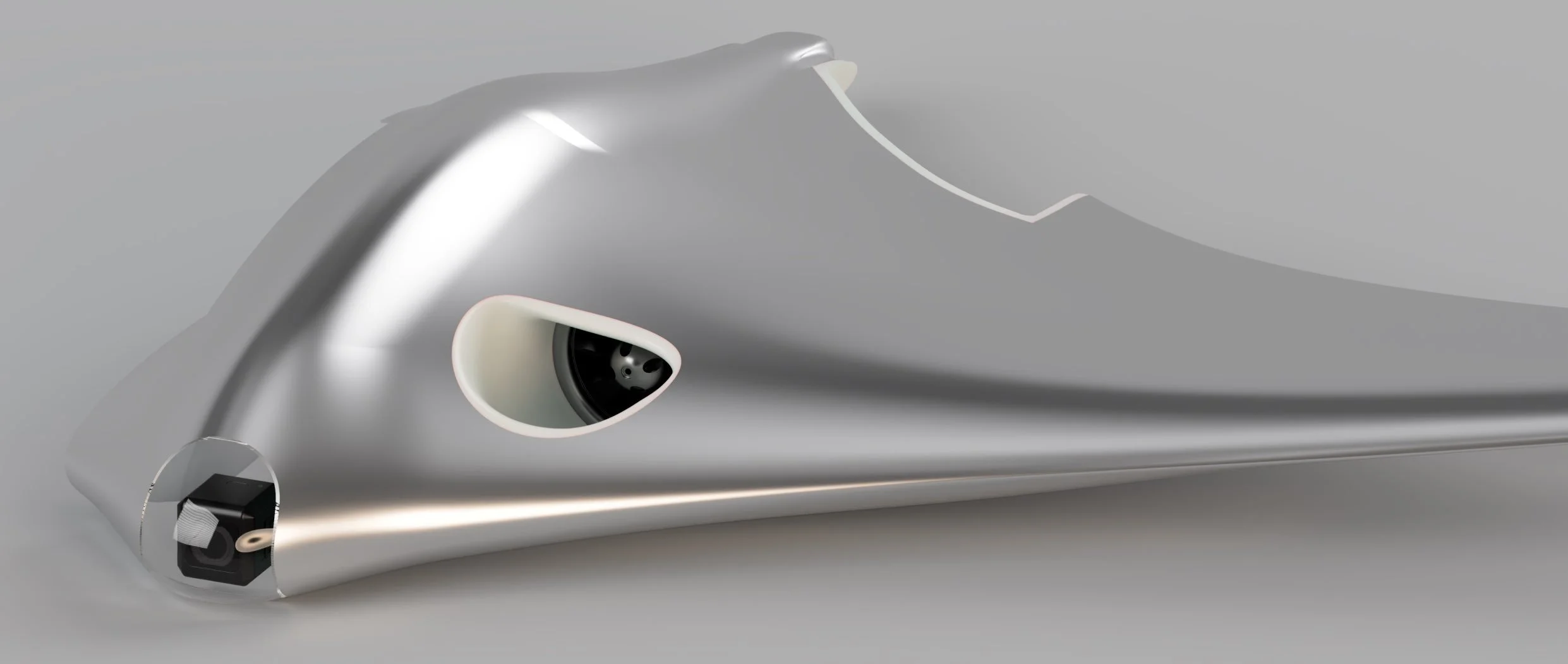
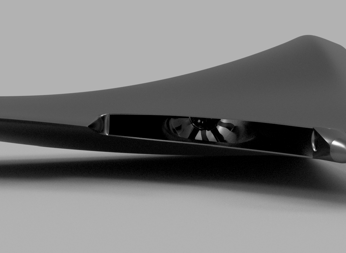
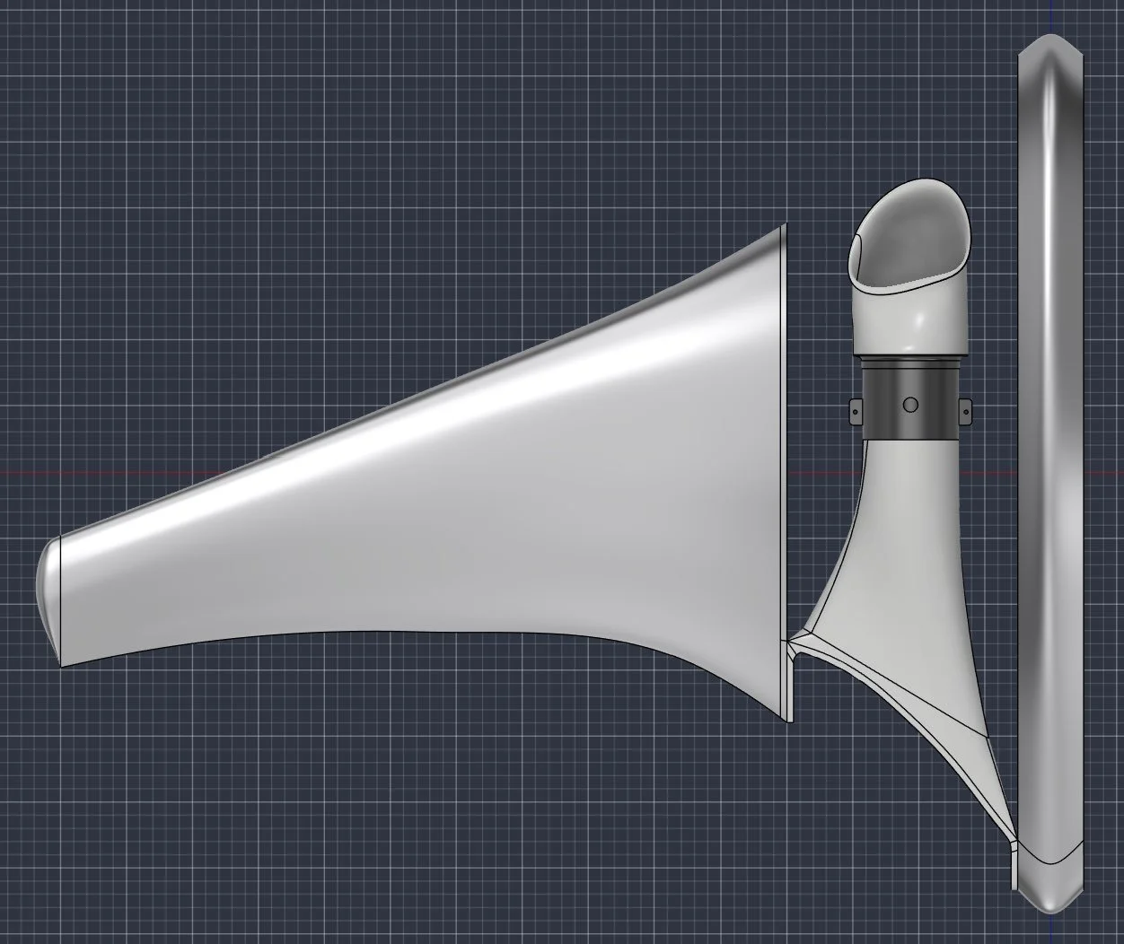
While I should have stopped there for version 1, I- at this point- wasn’t running CFD calculations after the aerodynamic body and instead put it off until I had completed the ducting and engine placement for the aircraft. Due to this, my next step was selecting an EDF. For this, I took different EDFs into consideration, eventually settling on a configuration of 2 medium-diameter EDFs, with a large removable battery in the middle of them. The selected EDF was 100mm in diameter and made of carbon fibre, reducing weight considerably compared to typical EDFs- approximately 1/3 the weight of comparable EDFs of the same diameter. These were placed centrally between the wing root and centre of the aircraft. After the placement was completed, a duct was added from the front, top surface of the wing, to the EDF’s intake, smoothed at the transition with a G2 fillet, and G2 duct geometry. At the EDF’s exhaust, it was ducted into a thin but wide channel, slightly higher in area than the EDF’s intake diameter. This exhaust duct was then exhausted in a cutout made at the trailing edge of the wing geometry, split equally between the top and bottom surfaces. This exhaust geometry had no G2 fillet to smooth the transition to the wing area, as it was unnecessary for outward flow and would further complicate manufacturability; instead, only the internal exhaust duct geometry was made with G2 surfacing.
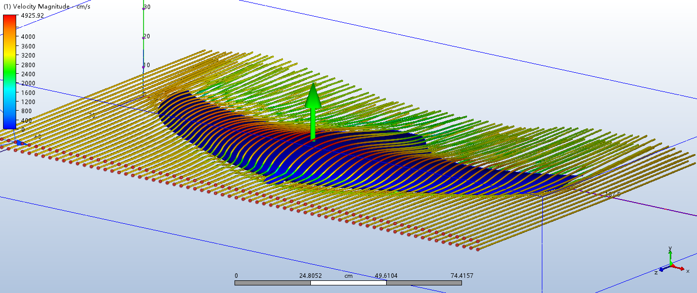
Once I had these components added, I finally decided to set up and run an Autodesk CFD run, where I ran into issues with creating a model for the simulation, as some of the geometry was unable to be used as-is, for a reason I am still unsure of, but it likely stems from my bad CAD practices for this first version. Because of this, I had to set up the solver to create a geometric, non-smooth mesh around the existing CAD geometry, so the solver could be run. The results in this were abysmal at flight conditions, likely stemming from four main issues: highly constrained CFD bounds, the rough geometry used for the CFD, the bad loft transitions between the incompatible airfoil sections, and the duct geometry and internal EDF- although I made sure to remove the blades for the CFD run.
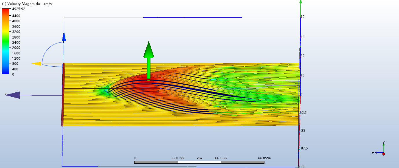
Moving on from Version 2, I completely changed my entire methodology for wing design in preparation for Version 3.
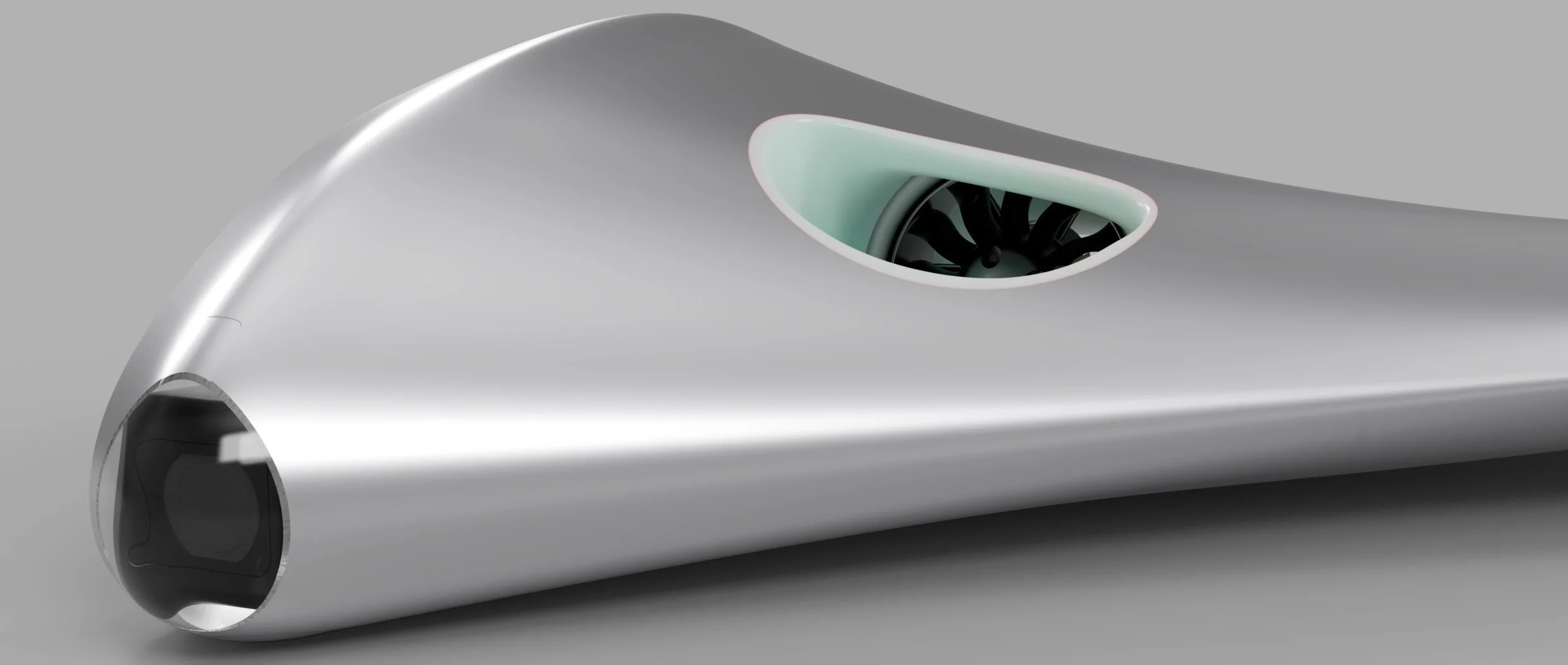
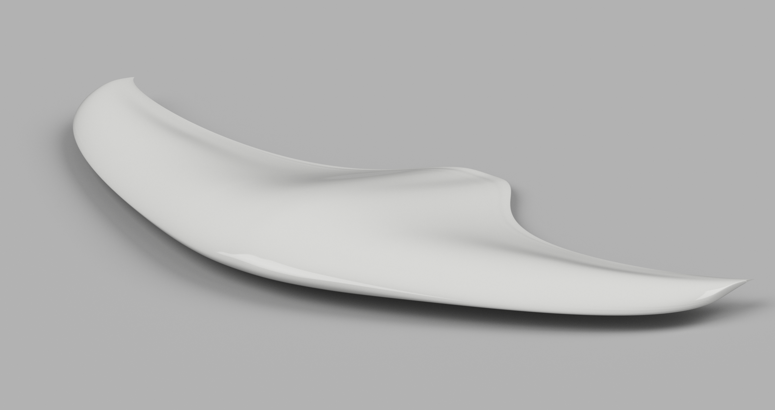
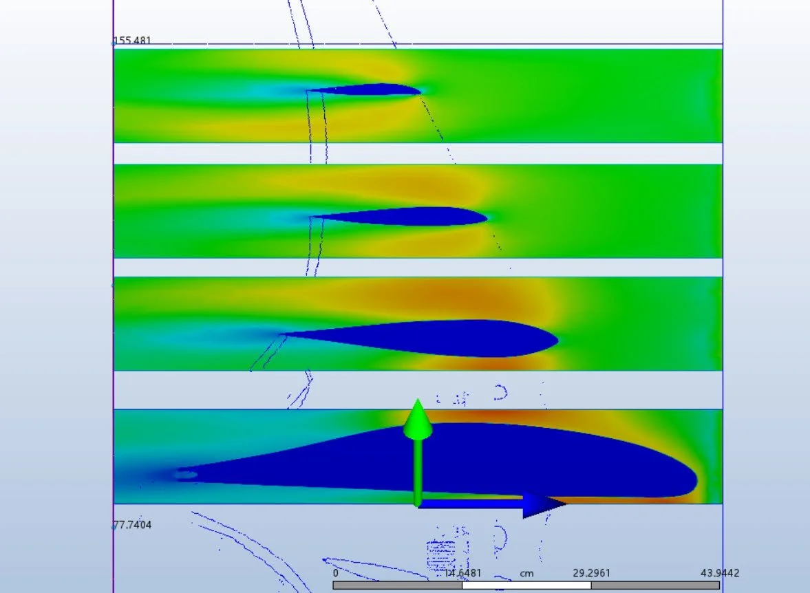
After running simulations on V1 and evaluating the design, I believed it would be best to fully restart the design from scratch, with an evolved methodology built from my mistakes and findings on V1. My main takeaways from V1 at this point were to evaluate the airfoils better individually. I believed that the individual airfoils caused the bad CFD results, and that I should evolve how I selected the airfoils independently. Moving on to V2, I would also ensure a run of an aerodynamic shell analysis- a CFD run right after I had completed the wings, with no ducts or breaks in the design- to see how just the wing selection would perform alone.
Selecting the airfoils for V2, I took around 3 possible options per airfoil section, keeping the 4 sections from the previous version. I compared each one, using a more in-depth per-airfoil analysis, comparing them with the other possible airfoils. For the fuselage, the only 2 main airfoils given serious consideration were the Davis Basic B-24 airfoil, and the Prandtl-D root airfoil; of which I chose the B-24 airfoil due to its lower Cd (at the given Reynolds number), better Cm characteristics, and smoother Cl/Cd graph, with a higher max Cl, even despite not having a great Cl or Cl/Cd ratio at cruise. Another main consideration was thickness, and the B-24 airfoil was slightly thicker than the Prandtl-D root airfoil, giving more space for EDFs between the center fuselage and wing root loft. With the wing root, I also decided to keep the B-24 airfoil, as the airfoil has relatively simple yet effective geometry, and would also be extremely strong for a wing root section. In my analysis of these airfoils, I also wrote about the transition geometry and how keeping both airfoils the same would keep the transition clean, but I did not yet weigh this transition highly enough compared to the individual airfoils of the wing design. After the root airfoil, the midwing airfoil selection came down to four major contenders- the Eppler E397, Althaus AH 95-160, Althaus AH 81-K-144/17, and Wortmann FX 76-MP-140. Between these four options, the AH 81 was chosen. It has great Cm compared to the Eppler and Wortmann airfoils, and compared to the AH 95, it has a much closer to 0 Cm as well. Beyond that, it has a slightly worse max Cl than the AH 95, but widens the alpha envelope by 3 degrees before stalling. The AH 81 also should have a reasonable transition from the B-24 airfoil, and maintains good characteristics to low Reynolds numbers, which the others can not due to the same degree. For my wingtip airfoils, I wanted to add slight washout, to promote the root-first stall behavior necessary for the wing. The selection came down to 5 options, including a windmill airfoil, but otherwise similar airfoils to the midwing selection. For the wingtip airfoil, I chose the Eppler E395; all the graphs for the airfoils were pretty similar at the same alpha, although the windmill airfoil- a Selig S4022- was slightly more robust, with a wider alpha envelope. Despite this, however, the E395 was the airfoil with the most favorable, non-erratic behavior at negative alphas, which is where the airfoil would likely be at cruise.
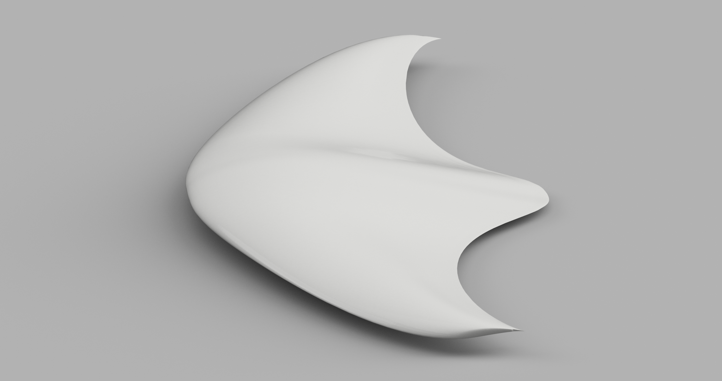
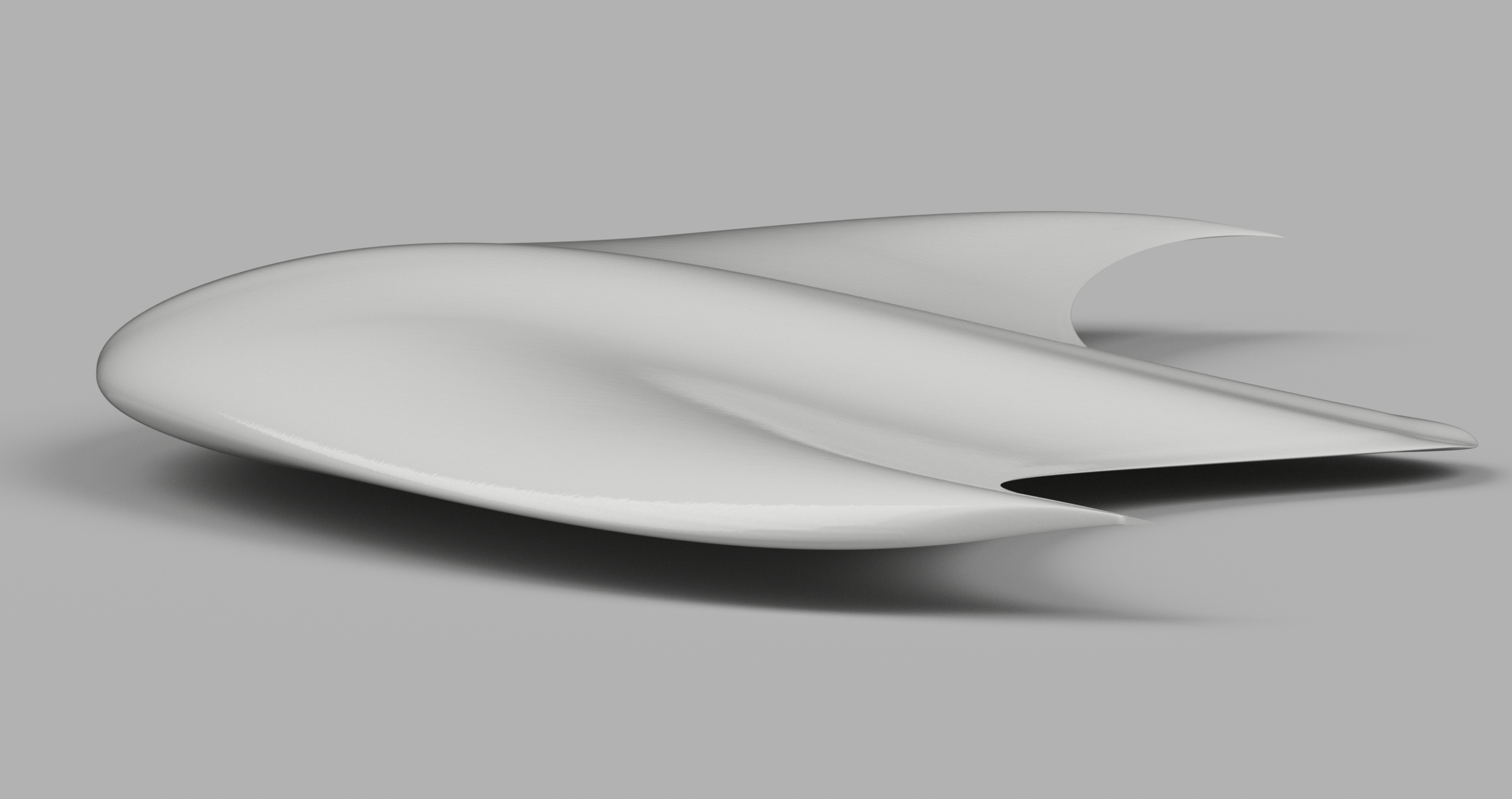
After selection for the airfoils, I brought them together to form a clean aerodynamic transition geometry, resembling a boomerang. For this version, I removed the sharp frontal transition seen in the first version, and kept the entire aircraft very smooth. For the airfoils specific rotation, I gave the fuselage and root airfoils a 3 degrees upward tilt while the aircraft is at 0 degrees alpha, and gave the Eppler 3 degrees washout; meaning a 6 degree transition between the root to the wingtip airfoil. Despite my hope of a cleaner, more predictable transition; and my better methodology in individual airfoil selection, as well as my angling of each airfoil, the aircraft’s aerodynamic skin still performed badly. If I were to have used this configuration, I would have been generating a lot of drag, and not much lift- requiring a lot of force to keep the aircraft moving, and likely cruising at a moderate alpha angle, rather than near-0 alpha.